Posts

Showing posts from 2008

Peak to Average Power Ratio II: An Introduction

Image
A Signal Processing Perspective The statistic properties of the PAPR of multi-carrier signals can be described by CCDF (Complementary Cumulative Distribution Function). If we assume the frequency-domain symbol is complex Gaussian distributed. When the number of subcarriers, L , become large, the instantaneous power of each multi-carrier signal chip can be modeled by a Chi-distributed signal with two degree of freedom. CCDF( γ ) = Pr( PAPR > γ ) = 1- Pr( PAPR <= γ ) = 1 – [ Pr( p <= γ ) ] L >~ 1 – ( 1 – e -γ ) L   Figure 1.  A statistic modeling of PAPR A Coding Perspective Given a code of length n , coding rate R, what is the achievable region of triplets ( R , d , PMEPR) ?  What is the relationship between PMEPR and the minimum Euclid distance (mED) d * ? All these questions belong to a Sphere Packing Problem. Given a codeset of q-ary code c with length n , what is the relationship between the size of the codeset and minimum Hamming distance (mHD) D ? This is a Sp

Peak to Average Power Ratio I: OFDM PAPR Reduction

[Contribution to 3GPP2 Next Generation Technologies Ad Hoc Group (NTAH) 2007] With the upcoming deployment of wideband wireless network with throughput greater than 100Mbps over high frequency bands such as 5-GHz band and the adopting of multicarrier modulations, more and more challenges are brought to system and hardware design. OFDM, frequently referred as multi-carrier modulation, is becoming the de facto standard for next-generation wideband wireless networks. However, one of the critical issues of OFDM as well as other multicarrier modulation scheme is its high peak-to-average power ratio (PAPR), which usually requires large backoff and highly efficient high power amplifier (HPA), large dynamic range analog-to-digital converter (ADC), high linearity up-converter, etc. These requirements lead to expensive hardware systems that are difficult to design. Hence it becomes more and more important to alleviate the burden of hardware design with employing advanced PAPR reduction technol

Interference Cancellation: IV A Blind Receiver Design Perspective

Image
[ Interference Cancellation. I. A Short Overview of Multiusr Detection ] [ Interference Cancellation: II. A Conventional Receiver Design Perspective ] [ Interference Cancellation: III. A Signal Subspace Perspective ] While the conventional signal model provides a foundation for both optimal and conventional multiuser receiver design and the subspace signal model aids understanding of the underlying signal structure, neither is simple enough for developing blind multiuser receivers for high-speed CDMA systems [Andrews 05]. In order to address the near-far problem with minimum prior knowledge and computational complexity, a blind multiuser signal model and blind multiuser receiver design framework are presented here. Within this framework, the blind receiver only requires several previously received symbols in addition to its own signal signature(s), amplitude(s) and timing(s). Different to the conventional multiuser model and subspace signal model [Verdu 98, Wang 98], there is no

Interference Cancellation: III A Signal Subspace Perspective

Image
[ Interference Cancellation. I. A Short Overview of Multiusr Detection ] [ Interference Cancellation: II. A Conventional Receiver Design Perspective ] [ Interference Cancellation: IV. A Blind Receiver Design Perspective ] In realities it is known to be difficult to directly and precisely estimate the signal signatures { s k : k ≠ 1} for taking advantage of well-developed optimum or conventional multiuser detection schemes. In Figure 1, the design of a linear MMSE interference cancellation receiver for CDMA systems is shown as an example. As we can see, there are at least two challenges in the implementation. The first one is you need know the signal signatures of all involved users. The second one is it requires the computation-intensive matrix inverse operation. Design challenges like these make the conventional interference cancellation methodology unattractive in practical applications. Figure 1. The challenges in employing conventional interference cancellation design. A

Interference Cancellation: II A Conventional Receiver Design Perspective

Image
[ Interference Cancellation. I. A Short Overview of Multiuser Detection ] [ Interference Cancellation: III. A Signal Subspace Perspective ] [ Interference Cancellation: IV. A Blind Receiver Design Perspective ] Introduction Interference cancellation provides a promising alternative to the conventional or optimum detectors in multiuser detection. Interference cancellation methods typically require less implementation complexity while practically o ering similar performance. The idea behind interference cancellation is to estimate the multiple access and/or multipath induced interference and then to subtract the interference estimate from the received signal. Hence, compared to other multiuser detection schemes, interference cancellation pays more attention on the estimation of the multiple access interference (MAI). Different schemes for the MAI estimation lead to different interference cancellation schemes. Actually, interference cancellation detector will cancel the interferin

Interference Cancellation: I. A Short Overview Multiuser Detection

Image
[ Interference Cancellation: II. A Conventional Receiver Design Perspective ] [ Interference Cancellation: III. A Signal Subspace Perspective ] [ Interference Cancellation: IV. A Blind Receiver Design Perspective ] [Toward Forward Link Interference Cancellation, CDMA Development Group (CDG) Technology Forum 2006] CDMA cellular network capacity is known to be interference-limited since the same spectrum is shared by many users and there exists a near-far problem due to multiple access interference (MAI). Multiuser receiver is highly regarded as one of the promising interference management techniques improving spectrum efficiency and achieving high-data rates for wireless multimedia communication. It has been intensively investigated over the last two decades and received much attention for next-generation radio access network [Andrews 05, Wang 05]. Optimum multiuser receivers and conventional multiuser receivers are known to be able to solve the near-far problem at the knowledge

H.264 Network Abstract Layer Header

RTP Packetization for H.264 NAL Units How to Broadcast Multimedia Contents? H.264 encoder is composed of two layers, video coding layer (VCL) and network abstraction layer (NAL). VCL translates the video information into bits streams. Since the underlying transportation layers are diversified, NAL maps VCL bitstreams into byte-oriented transportation-layer-friendly and HDLC-like NAL units prior to delivery. During the mapping of VCL bitstreams to NAL units, at least three operations are done, which are byte alignment, emulation prevention, framing with an additional one-byte NAL unit header. The first byte after a NAL unit start code prefix is the NAL unit header. A NAL unit header consists of  three fields. forbidden_bit (1 bit) : may be used to indicate a NAL unit is corrupted or not. nal_storage_idc (2 bit) : signals relative importance, and if the picture is stored in the reference picture buffer.  nal_unit_type (5 bit) : signals 1 of 10 different NAL unit types. H.264 d

How to Broadcast Multimedia Contents? II Lessons from The Channel

Image
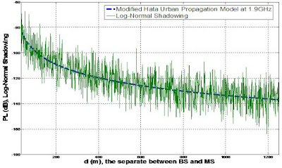
What Is The Next for Mobile System Design? I A Single-Cell Model Perspective on Downlinks [How to Broadcast Multimedia Contents? I Introduction] [How to Broadcast Multimedia Contents? IV Hierarchical Modulation] [How to Broadcast Multimedia Contents? V Overloaded Transmission and IC] [How to Broadcast Multimedia Contents? VI Open-Loop MIMO for BCMCS] [How to Broadcast Multimedia Contents? VII Network Layer or Stream Layer Design] COST 231 model, which was developed by European COST Action 231, and its variations are the most popular radio propagation model adopted in various standardization bodies, such as 3GPP, 3GPP2 and IEEE. Its modifications include COST 231-Hata Model and COST 231-Walfisch-Ikegami Model . The mathematical formulation of the COST 231-Hata model path loss in dB is PL = 46.3 + 33.9 logf - 13.82log h BS - a( h MS ) + [ 44.9-6.55logh BS ] log d + C which features a carrier frequency f between 800MHz and 2GHz, an above-neighborhood base station antenna w

How to Broadcast Multimedia Contents? I Introduction

Image
What Is The Next for Mobile System Design? I A Single-Cell Model Perspective on Downlinks [How to Broadcast Multimedia Contents? II Lessons from The Channel] [How to Broadcast Multimedia Contents? IV Hierarchical Modulation] [How to Broadcast Multimedia Contents? V Overloaded Transmission and IC] [How to Broadcast Multimedia Contents? VI Open-Loop MIMO for BCMCS] [How to Broadcast Multimedia Contents? VII Network Layer or Steam Layer Design] Broadcast multicast service (BCMCS) has increasingly been popular for delivering multimedia content to mobile users. Traditional digital broadcast air interfaces are designed with the tradeoff between maximum achievable rate and intended coverage in mind. The actual rates are usually limited by the maximum transmit power and the worst channel condition so that every user in coverage can reliably receive the services as well as contents of same quality. The users under good reception condition may have no advantage, even if their potential

Location Based Services for Mobiles II: GPS, Assisted GPS and Network Assisted GPS

Image
[IEEE C802.16m-08/1105 Network Assisted GPS (N-GPS) Positioning in WiMAX/16m] [Location Based Service for Mobiles I: Technologies and Standards] GPS - Global Positioning System Figure 1. GPS System Archiecture: Space Segment, Control Segment and User Segment GPS is a Global Navigation Satellite System for determining the positions of receivers using signals broadcast by satellites.  It was developed and operated by US government to enhance the effectiveness of allied and US military forces.  The first experimental Block-I GPS satellite was launched in 1978. Since 1983, GPS has become an aid to civilian navigation worldwide, and a useful tool for survey, commerce, and scientific uses.  As of September 2007, there are 31 actively broadcasting satellites in the GPS constellation.  Satellites orbit 20,163 kilometers above the earth at 3.87 km/s.  6 orbital planes, each with 4+ satellites. Typically 6 to 12 satellites are visible from any place on the earth.  GPS based po

Location Based Services for Mobiles I: Technologies and Standards

[Tutorial in IEEE International Conference on Communications (ICC) 2008] [Location Based Services for Mobiles II: GPS, Assisted GPS and Network Assisted GPS] [How to Improve Forward Link Positioning ... ? I. Introduction] [How to Improve Forward Link Positioning ... ? II. Hearability and Accuracy] [1x HDP Enhancements] [Enhanced Location Based Services Support in cdma2000] [IEEE C802.16m-08/1106 Enhance Downlink Positioning in WiMAX/16m] [IEEE C802.16m-08/1105 Network Assisted GPS (N-GPS) Positioning in WiMAX/16m] Location based services (LBS) for mobile are the services supported by cellular networks for providing mobile users with various location sensitive applications such as E911, Friendfinder, personalized advertisement, etc. LBS accelerate the convergence of 3C (computer, communication and consumer electronics). One aspect of LBS market is the rapid growth of GPS market, which is predicted to reach $28.9 billion by 2010 by GPS World. It is believed that LBS is bringing